Wyprowadzenie IDE
From Atariki
(Różnice między wersjami)
| Wersja z dnia 13:40, 10 lip 2005 KMK (Dyskusja | wkład) ← Previous diff |
Wersja z dnia 12:01, 6 wrz 2005 Mikey (Dyskusja | wkład) Next diff → |
||
| Linia 63: | Linia 63: | ||
| [[Kategoria:Atari 8-bit]] | [[Kategoria:Atari 8-bit]] | ||
| + | [[Kategoria:Schematy i specyfikacje]] | ||
Wersja z dnia 12:01, 6 wrz 2005
To zaproponowany przez Pasia standard wyprowadzenia IDE na zewnątrz obudowy Atari. Zastosowane 50-pinowe żeńskie gniazdo Amphenol jest popularne, tanie i zapewnia dużą niezawodność.
Widok na gniazdo patrząc na tylną ściankę komputera.
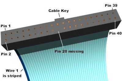
Widok na taśmę IDE.
Schemat połączeń w kablu:
40pin IDE Connector	- 50pin Amphenol

 1 (Reset)	          -  1
 2 (Ground)	          - 26
 3 (Data Bit 7)		  -  2
 4 (Data Bit 8)		  - 27
 5 (Data Bit 6)		  -  3
 6 (Data Bit 9)		  - 28
 7 (Data Bit 5)		  -  4
 8 (Data Bit 10)          - 29
 9 (Data Bit 4)		  -  5
10 (Data Bit 11)          - 30
11 (Data Bit 3)		  -  6
12 (Data Bit 12)	  - 31
13 (Data Bit 2)		  -  7
14 (Data Bit 13)	  - 32
15 (Data Bit 1)		  -  8
16 (Data Bit 14)	  - 33
17 (Data Bit 0)		  -  9
18 (Data Bit 15)	  - 34
19 (Ground)		  - 10
20 (Cable Key - pin missing
21 (DRQ 3)	          - 11
22 (Ground)		  - 36
23 (-IOW)		  - 12
24 (Ground)		  - 37
25 (-IOR)		  - 13
26 (Ground)		  - 38
27 (I/O Channel Ready)	  - 14
28 (SPSYNC: Cable Select) - 39
29 (-DACK 3)		  - 15
30 (Ground)		  - 40
31 (RQ 14)		  - 16
32 (-IOCS 16)		  - 41
33 (Address Bit 1)	  - 17
34 (-PDIAG)		  - 42
35 (Address Bit 0)	  - 18
36 (Address Bit 2)	  - 43
37 (-CS1FX)		  - 19
38 (-CS3FX)		  - 44
39 (-DA/SP)		  - 20
40 (Ground)		  - 45


